Custom Hand Visuals
The plugin provides methods for rigging hand models, using either our default rig or using a rig of your own.
This guide is a little more technically involved than others in this feature section. However, if you have a good understanding of rigging in your chosen tool. it should be easy enough to follow along.
Note
Sample scene can be found in:
Assets/Samples/Ultraleap Tracking/x.x.x/XR Examples/1. Basics/1. Hand Model Showcase.unity
Included examples of rigged hands
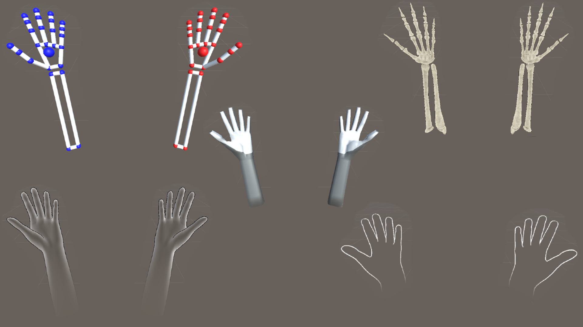
The Ultraleap Unity Plugin comes with a set of pre-rigged hand models, including; low poly hands, generic hands and skeleton hands. Each can include forearms and are ready to use. Combined with shaders and materials, you can quickly have outline hands, ghost hands and stylized hands in your project.
You can find the selection in Packages > Ultraleap Tracking > Hands > Runtime > Prefabs.
Read on if you would like to create or use your own hand models with the Ultraleap Unity Plugin.
Rigging Hands
Please choose one of the tabs below depending on whether you would like to use our default bone set to add your own flavour to, or rigging your own model with as many joints or fingers you’d like.
In the Unity Plugin, we provide a skeleton in a default hand pose, that already has all bones named following the naming convention. The easiest way to rig you custom hand mesh is to use that skeleton. You can find it under Packages/Tracking/Hands/Runtime/Models/LeapReferenceHand.fbx.
This video shows a step-by-step on how to use it for a custom hand model in Blender. Below you can find more information for each step:
How To
Open or create your hand mesh in Blender & import the LeapReferenceHand.fbx
Make sure to have your hand mesh open
Click on File -> Import -> FBX, navigate to Packages/Tracking/Hands/Runtime/Models and choose LeapReferenceHand.fbx to import
Fit the skeleton to your mesh
Make sure that the skeleton and the mesh line up approximately by scaling, translating, and rotating either the mesh or the skeleton
Useful Blender shortcuts: R - rotate, G - grab / translate, S - scale
Move each bone to sit in the correct position relative to your hand mesh
Select the skeleton and go into Edit Mode
Move all bones to the correct positions (for more info on where the correct position is, see Joint Placement in Rigging Hand Assets from Scratch)
Useful Blender tips: Using G and any of X, Y or Z afterwards, will allow translation only along the specified axis. Toggle between bones being visible in front of the mesh by selecting the skeleton, clicking on Object Data Properties and choosing In Front under ViewPort Display.
Parent the skeleton to the mesh (with automatic weights)
Select the mesh, then shift-select the skeleton
ctrl + p will open a parenting menu. Choose Armature Deform with Automatic Weights
Use Pose Mode to test the bone weightings
Select the skeleton and go into Pose Mode
Select some bones and rotate (R) them to make sure that the parenting worked and that the bone weights are correct
(Optional) Edit the Weight Painting for each bone
Select the mesh and go into Weight Paint mode. If you also open the Object Data Properties tab, that makes it easy to select different bones to edit their weight painting.
Edit the Weight Painting for each bone until you are happy with the way the hand moves in Pose Mode. Make sure that the wrist bone doesn’t affect the elbow mesh, and that none of the fingertips affect the mesh at all. Each bone should affect the mesh above its position. For example, the distal bone should affect the mesh between the distal bone’s position and the finger tip.
Export as an fbx
Make sure you don’t have any models or lights in the scene other than the hand
Click on File -> Export -> fbx, choose a location and name and click export
Import the fbx into Unity
Open Unity and drag the exported fbx into the Assets Window
Drag it into your scene, Add a HandBinder component and Auto-Bind
Create a new scene and add a Service Provider (Desktop) Prefab to it
Drag the new fbx into the scene and make sure that it shows up correctly in the scene view
Select it and in the Inspector, click Add Component, search for the HandBinder and add it
In the new Hand Binder Component, click on Bind Hand and then Auto Bind. The hand model should now be moved to the default position and pose
Optionally, you can now edit settings on the Hand Binder such as finger tip offsets or hand scale
Connect a device, hit play and see your custom hand model following your real hands’ movement
Troubleshooting
The model in Unity is very big or very small, or the axes point in the wrong direction
Make sure that you use Blender’s default export settings: In the export window, you can toggle off / on export settings by clicking the gear in the top right corner. Click on Operator Presets and then on Reset Operator Defaults.
In Unity, you can also change the import settings: Click on the fbx in Project View, then you can change import settings like scale or units in the Inspector.
The model doesn’t follow the tracking data nicely in Unity and, for example, bending a finger does not affect the mesh the way you would expect it
Double check the weight painting in Blender and make sure that each bone affects the right area of the mesh. Sometimes the automatic weighting requires some manual adjustments of the weights on some vertices of the mesh. Make sure that the finger-tips don’t affect any of the mesh. They are there for reference rather than for manipulating the mesh.
We’re very keen to support you in making your own hand assets, so we’ve put together this guide to the principles for rigging your own creations.

Use our rigging guide to get your sketches off the page and attached to our tracking data
If you’ve got some experience with modelling and you want to get a bit more technical, you’re in the right place.
This page will:
Show you how to rig your own hand assets so they work with our tracking data.
Detail how to use our new Hand Binder pipeline, as well as some of what happens under the hood.
Break down the 3D rigging process and walk you through how to connect to the 27 possible data points of the hand.
Cover some best practices for both building hand assets from scratch or using hand assets from a 3D asset store.

Your hand doesn’t need to have the typical number of fingers and thumbs… or even be a hand. You rig your creation the way you want, and you decide how it works with our tracking data
It doesn’t matter which modelling package you’re using. We use Autodesk Maya, so some of the screenshots we use show the Autodesk Maya interface. The rigging principles are the same across different modelling environments even though the terminology may differ.
To make things nice and clear, we’re going to demonstrate on a 3D model of a skeleton hand.

Connecting to the 27 Data Points
We can use the positional and rotational data from the following points to connect to our rigged 3D Hand.
Wrist
Thumb_Meta
Thumb_Proximal
Thumb_Intermediate
Thumb Distal
Thumb_Tip
Index_Meta
Index_Proximal
Index_Intermediate
Index_Distal
Index_Tip
Middle_Meta
Middle_Proximal
Middle_Intermediate
Middle_Distal
Middle_Tip
Ring_Meta
Ring_Proximal
Ring_Intermediate
Ring_Distal
Ring_Tip
Pinky_Meta
Pinky_Proximal
Pinky_Intermediate
Pinky_Distal
Pinky_Tip
Elbow
We cross out Thumb_Meta because its data is identical to the Thumb_Proximal. You can include a Thumb_Meta if you wish, but your 3D Hand will give you the same results.
You don’t need to use all 27 points. Maybe your hand has fewer than the usual number of fingers, or maybe your ‘hand’ isn’t a hand. If your hand is a clamp or a claw you won’t need 1:1 mapping. Within your game engine you can connect to just 1, or all of these joints. Whatever works.
Joint placement

Now that we know what data we can use, it’s time to decide where we should position each bone/pivot onto our 3D model.
Each joint will contain a gizmo that points towards the next bone. Using this you can line up the joints so they sit in the centre of the mesh. Change the viewport to top down view and enable Projected Centering. Projected Centering estimates the centre of a mesh volume to help you position your joints.
Each time you make a new joint it will assign the previous joint you made as the parent. This relationship is visually identifiable - as you can see below, each metacarpal joint (connecting the palm to the fingers) is attached to the single parent wrist bone.

It’s important to think carefully about where you want the bone to pivot around. In this example you can see each new bone is at the end of the previous bone.
Joint Orientation
So now the bones are in the correct place, the next step is to make sure they are all pointing the right way. This process, called orienting joints, makes sure that the rotation axis is set up for how you’d like the geometry to rotate around the joint.
Make sure each joint is orientated so that :
The Primary/Forward axis points down the bone towards the next bone of the hand.
The Secondary/Up axis points out the top of the hand.
The final axis will point out of the finger either to the left or the right of the hand model.
The tracking data has been defined so that:
Z - Points down the bone.
Y - Points up out of the bone.
X - Points to the left of the bone.
To achieve this in Maya, you can set the Orient Joint Option to these values. If you turn on Orient Children of Selected Joints it will also automatically orient any children of the bone you have selected.
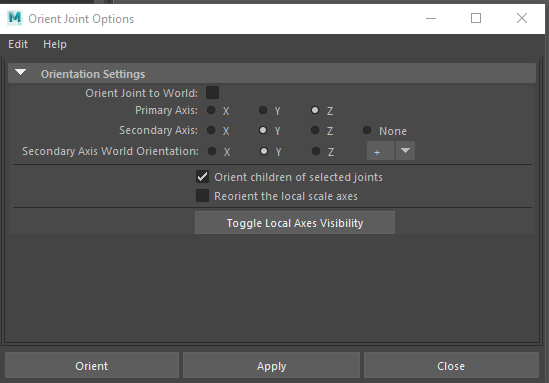
It’s important to inspect the geometry of your model as you rotate joints. Think about how you want the geometry to move once it is attached to that joint. Make sure each axis lines up with how you would expect it to rotate around.
We’ve found that Maya has really helpful little graphics that show you the rotation axis of each joint. Below is a screenshot of the Local Rotation Axis of the bones on the index finger.
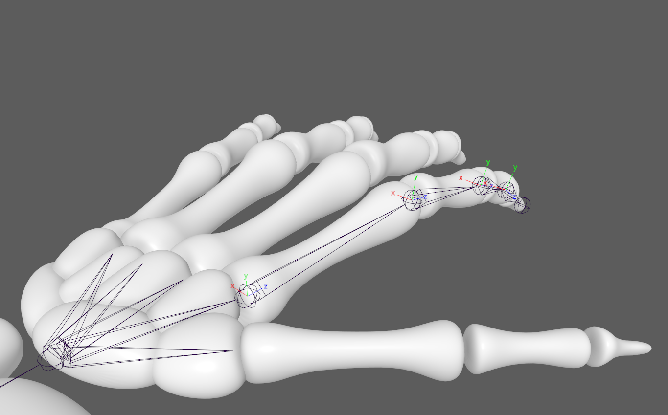
As we rotate the joint on each axis, we can see how the bones will rotate when attached to the tracking data.
In comparison, you can see how this joint with an incorrect rotation axis will behave.
Helpful tips for Maya users:
Once you have orientated all the joints, make sure you freeze the joint transformations. Doing this sets the current rotation of the selected joint as zero. This means if you accidentally rotate the joint, you can restore it back to the rotation you specified after following the steps above.
Set the preferred angle. This will store the orientation of the joints for you. You can then hold down right click over the topmost joint and select Assume Preferred Angle to reset the entire joint structure back to how you have just positioned and orientated it.
Weight Painting/Skinning
Now you’ve got the joints positioned and orientated onto your model, the next step is attaching the geometry to these joints. To do this, you are going to follow the process of weight painting - sometimes referred to as skinning. Weight painting is the process of assigning a weight to each vertex of a model. This weight is between 0-1 and is the amount each joint will affect that vertex.
Note - After binding the geometry to the joints you should not be changing the geometry in any way.
To bind the geometry, select the top-most joint and the geometry you wish to bind. Then select Bind Skin from the Skin Options menu.
When you bind the joints for the first time, you might notice that the geometry is not connected very well. To fix this, inspect the weight paints and see which joints are connected to which vertices of the model.
In the picture below we can see the wrist bone is currently affecting the radius bone of the model. While this may look correct, it’s important to note that joints work down the bone. In other words, the wrist joint should only be affecting geometry between itself and the next bone in the chain.
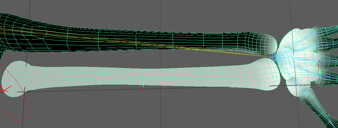
You can clearly see the impact of getting this wrong in the clip below. If the wrist joint had the weighting shown above, the result would look something like this:
To fix this, we need to select the joint before the wrist, then give all the vertices of the Radius and Ulna a weighting of 1. Notice in the video below that when we rotate the wrist this time, the geometry stays in the correct place.
Once you’ve assigned the correct weights to each joint, test by moving the joints around. Pay attention to how the joints and geometry move together.
Joint naming
Next, name your joints. Simply select a joint in the Outliner and type the name.
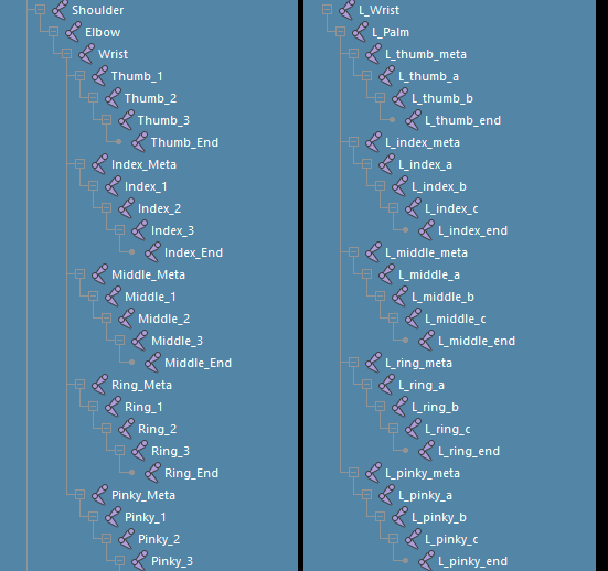
A few examples of naming conventions are shown below but for best results follow the naming convention outlined in Connecting to the 27 Data Points.
Joints that are named joint1, joint2 …etc. will not work with our auto rigging scripts and you will need to manually assign each bone.
Let's Have A Show Of Hands Please
And that’s it! We’d love to see your creations. Weird, wonderful, hyperrealistic, monstrous or otherwise. You can find us on Discord or if you are experiencing issues you can email support@ultraleap.com.