3Di Mounting Solutions
There are a series of different mounting solutions for the Ultraleap 3Di. To explore further options, obtain a CAD file of any of the mounts or for support please contact us via support@ultraleap.com.
Multi Mount
The Multi Mount holds the Ultraleap 3Di securely to kiosk or screen, and can be used in desktop mode. It provides optimum camera placement for evaluation and deployment. Designed by Ultraleap’s team of engineers, it can be attached to a wide range of displays with straight forward installation, minimal retrofitting and easy cleaning. The Multi Mount can also sit on any horizontal surface to support desktop evaluation or deployments.
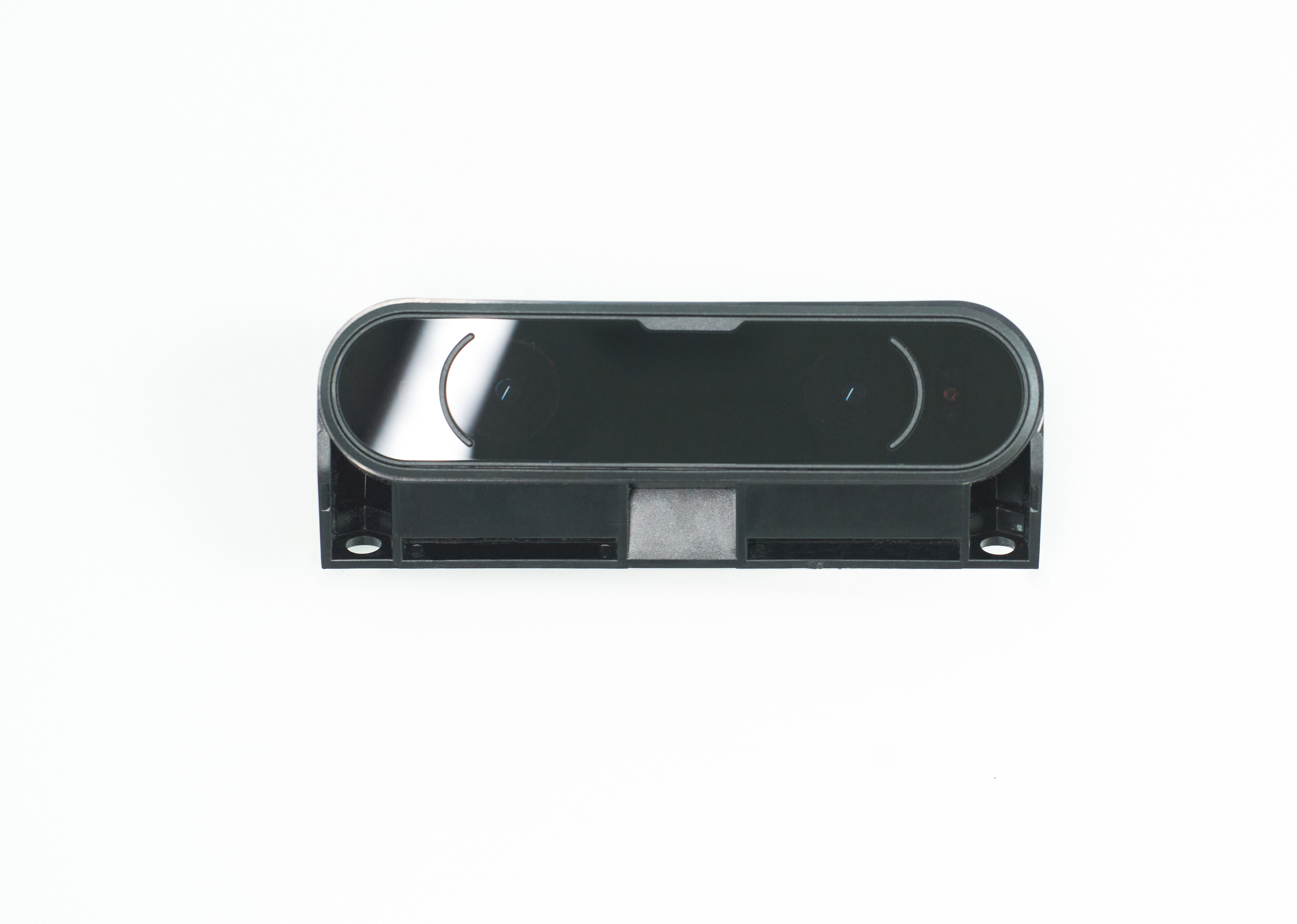
Multi Mount and Ultraleap 3Di.
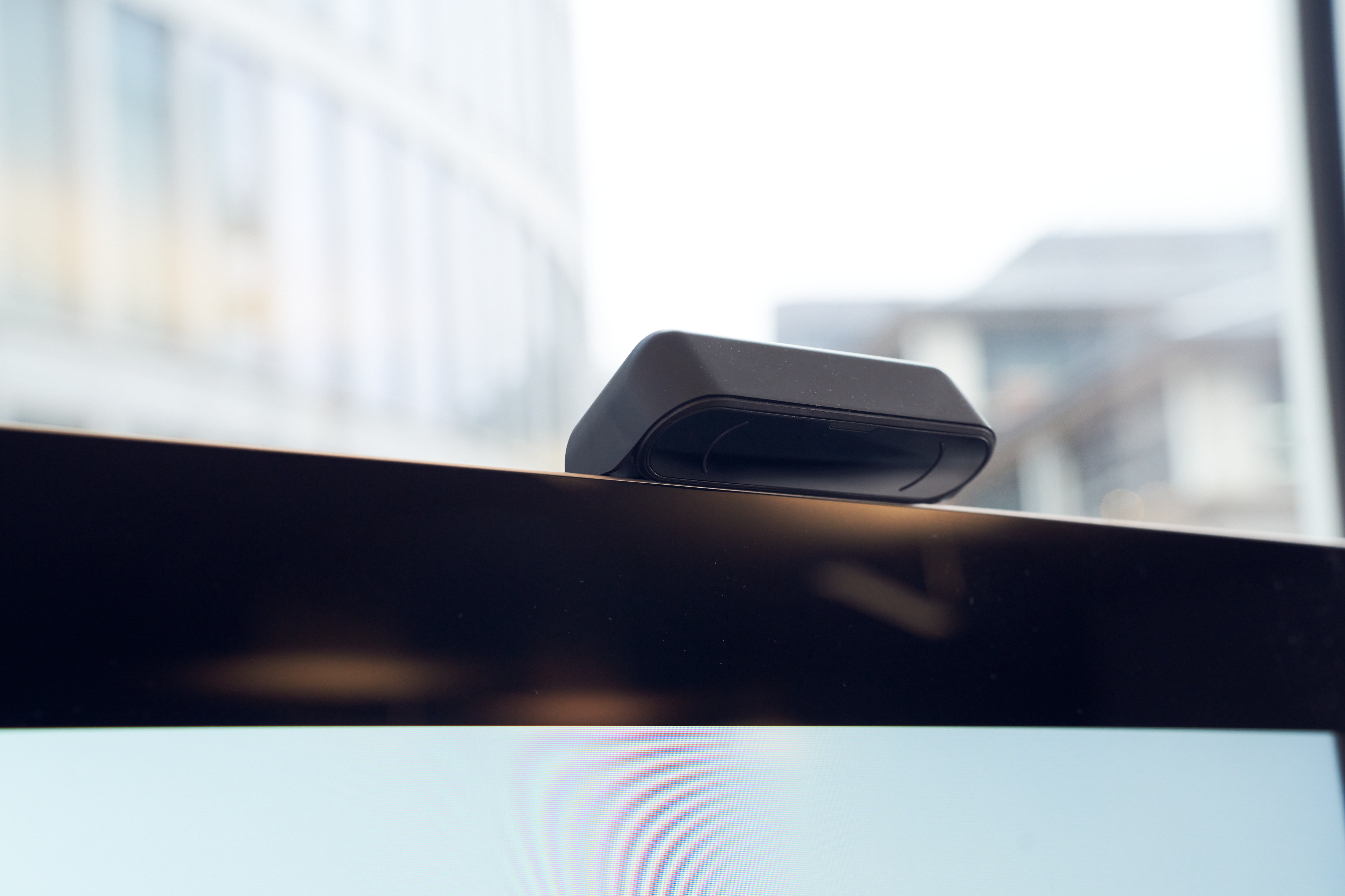
Ultraleap 3Di fitted to screen with the Multi Mount.
Attaching Ultraleap 3Di to Multi Mount
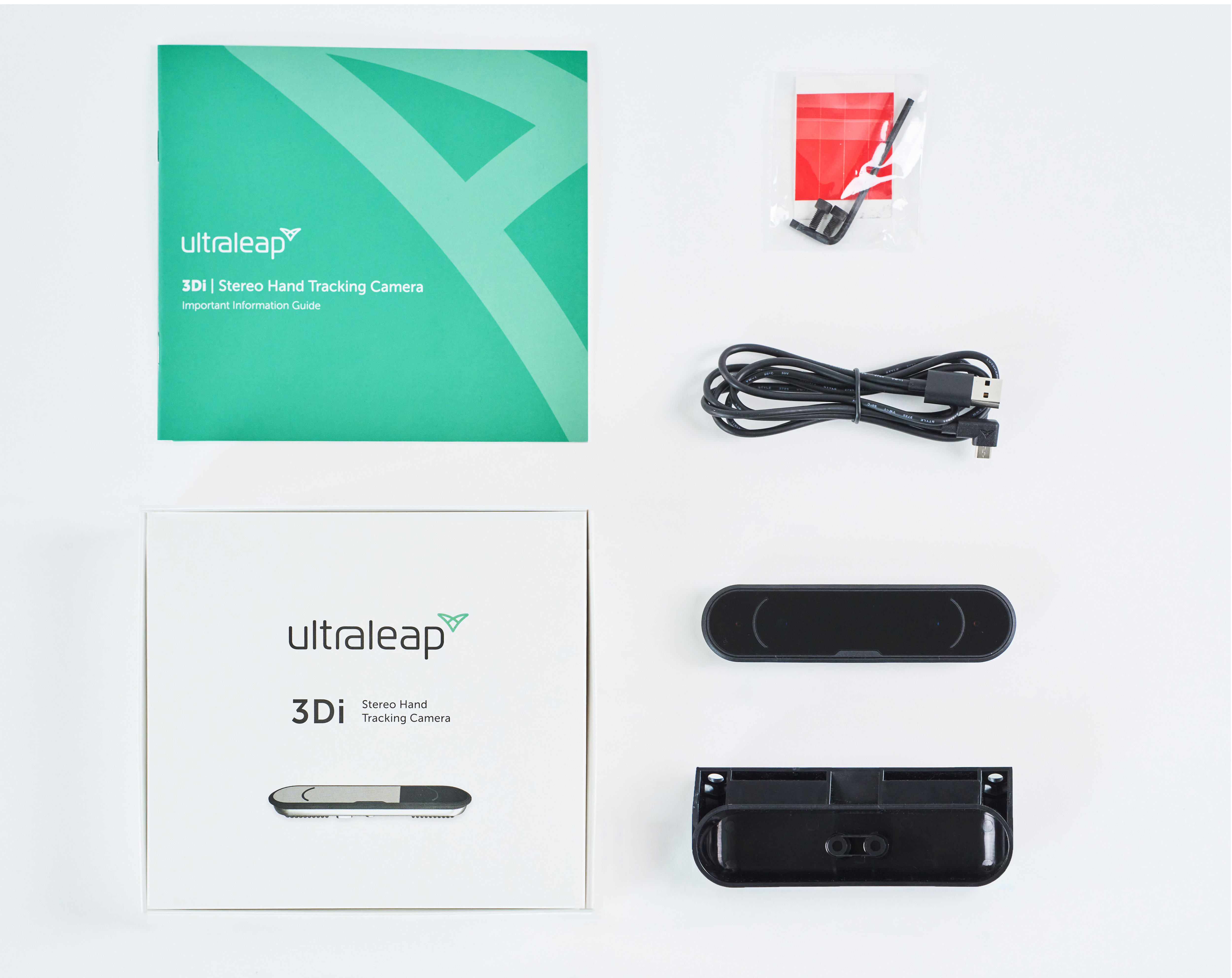
What’s in the box
Ultraleap 3Di Stereo Hand Tracking Camera
USB 2.0 cable*
Multi Mount for 3Di*
4x Adhesive strips for attaching Multi Mount to surfaces*
2x M4x8 cap head screws for securely attaching 3Di to Multi Mount*
Hex key*
* Not included in volume orders.
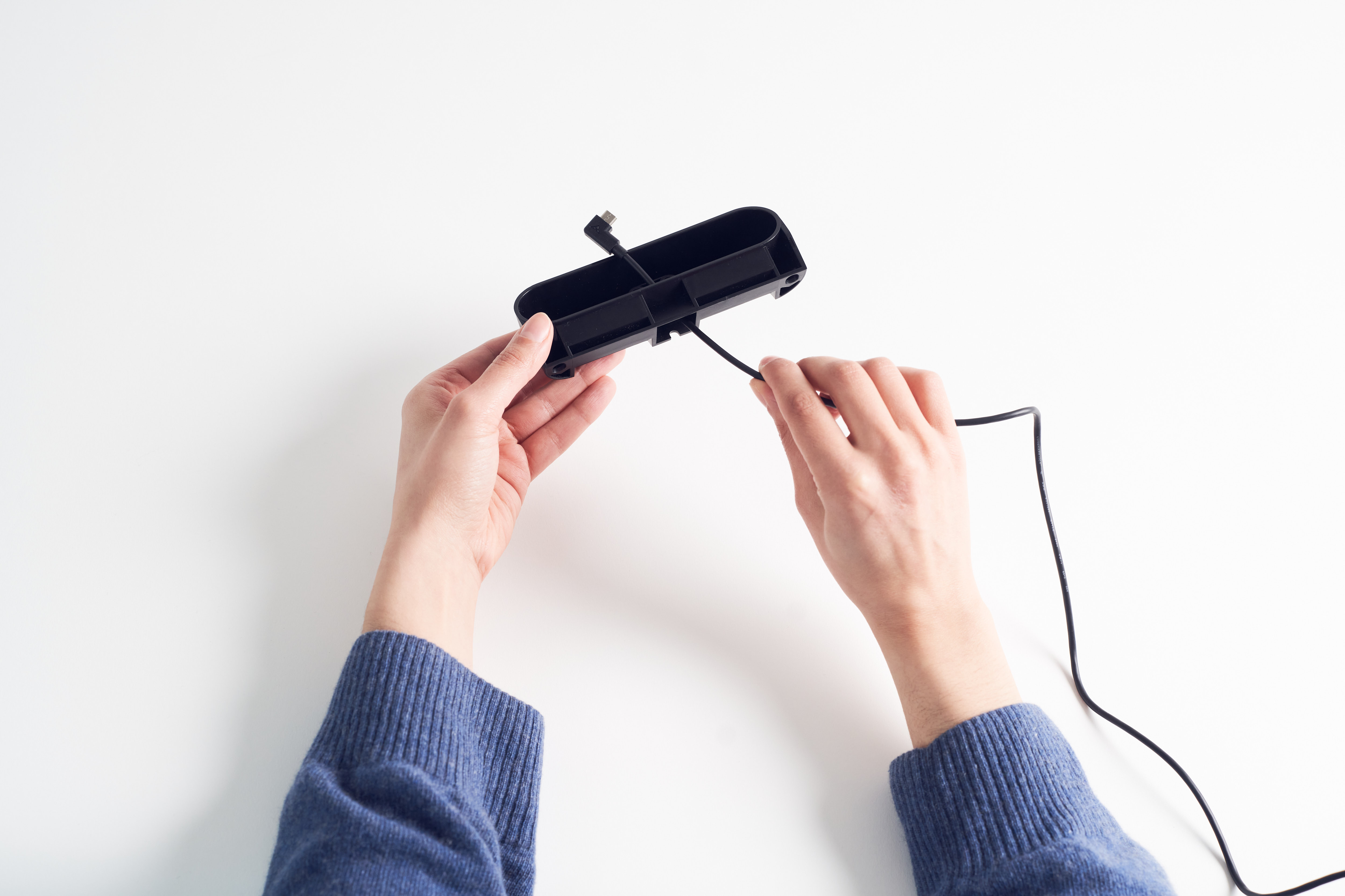
Step 1
Feed USB cable through access hole at rear of the Multi Mount.
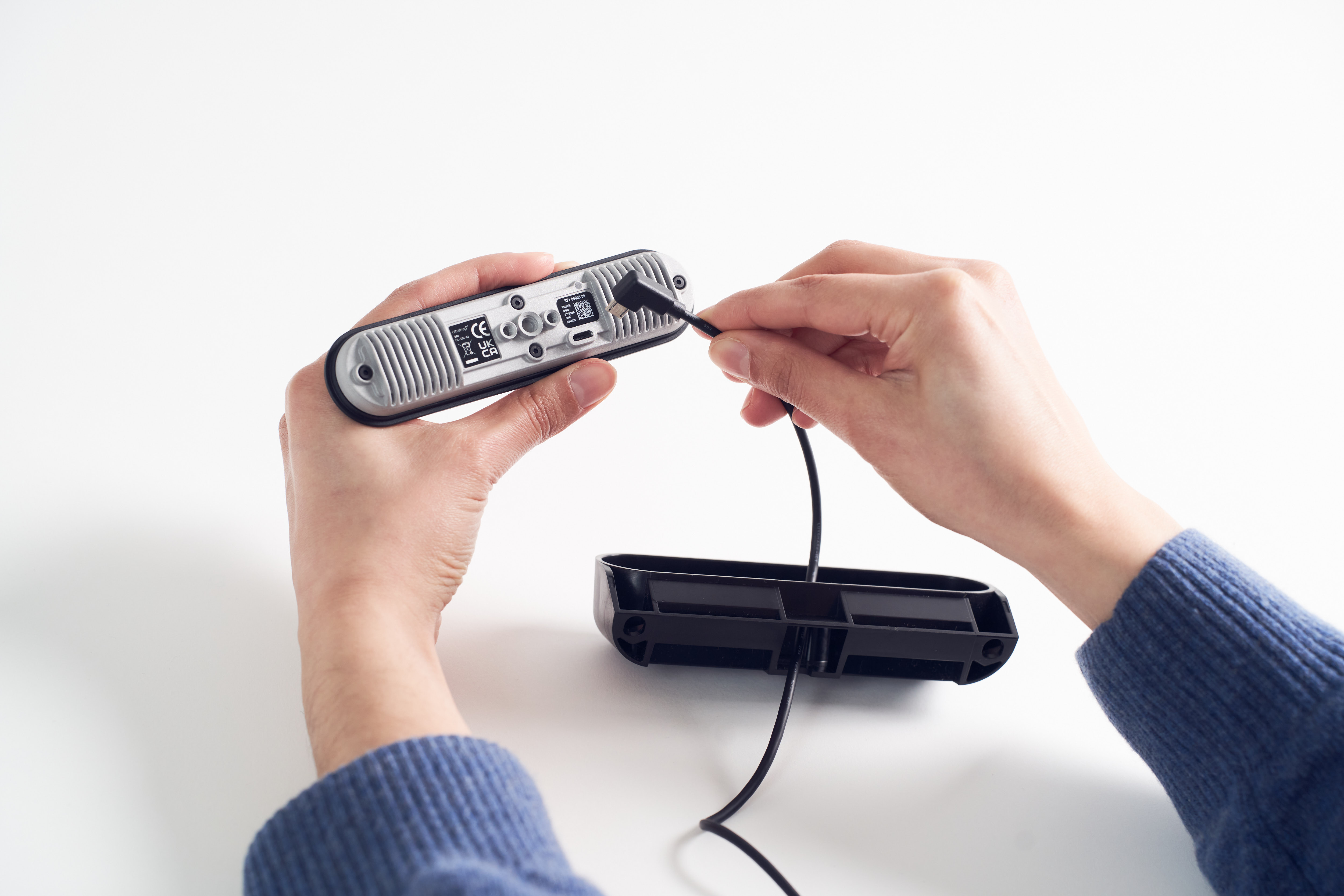
Step 2
Plug USB cable into the Ultraleap 3Di camera module.
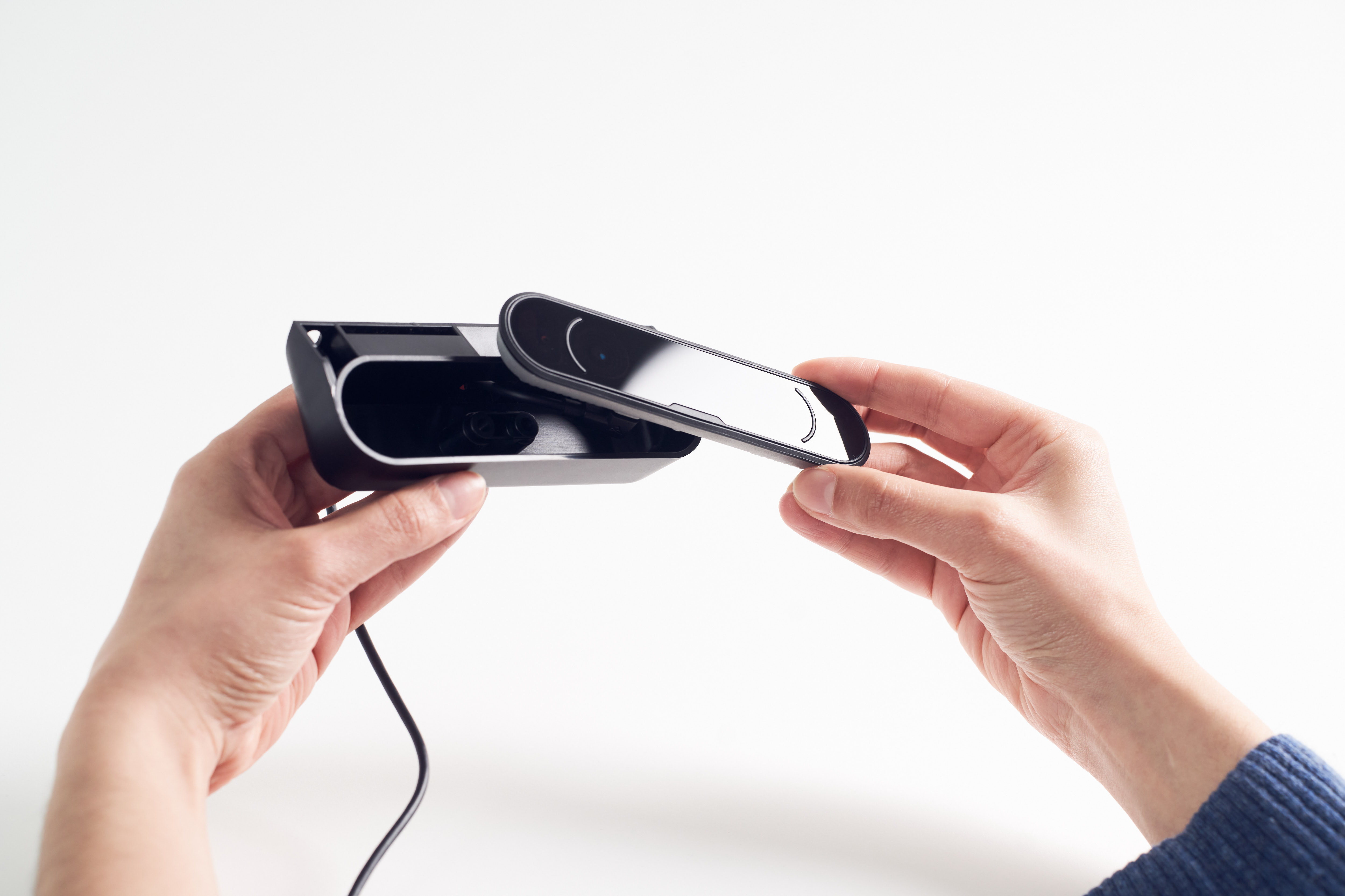
Step 3
Taking care not to catch the USB cable, place the Ultraleap 3Di in the Multi Mount ensuring the matte notch on the screen is placed on the opposite side from the cable exit.
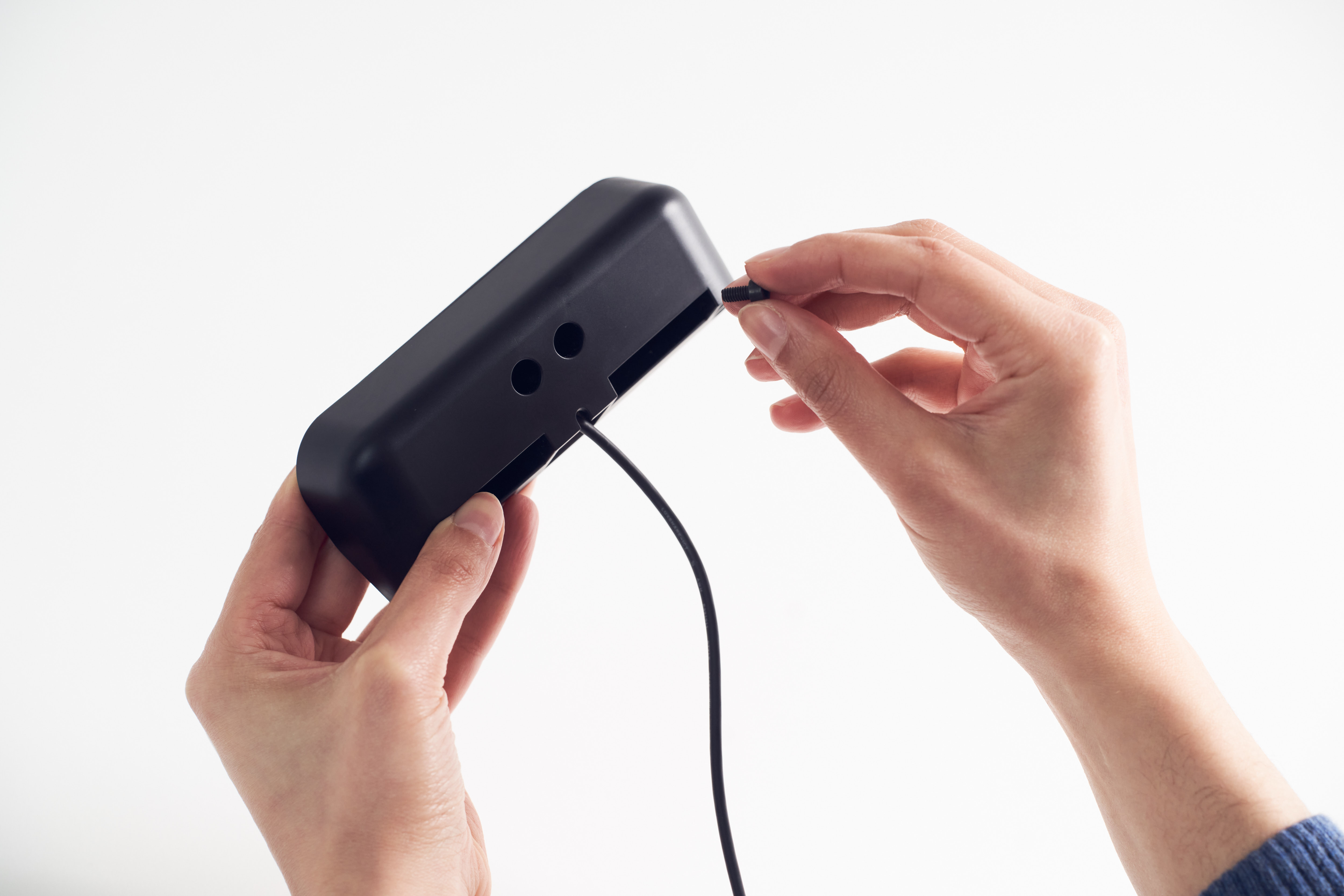
Step 4
Using the hex key and bolts provided, secure the Ultraleap 3Di to the Multi Mount. Take care not to over tighten the bolts.
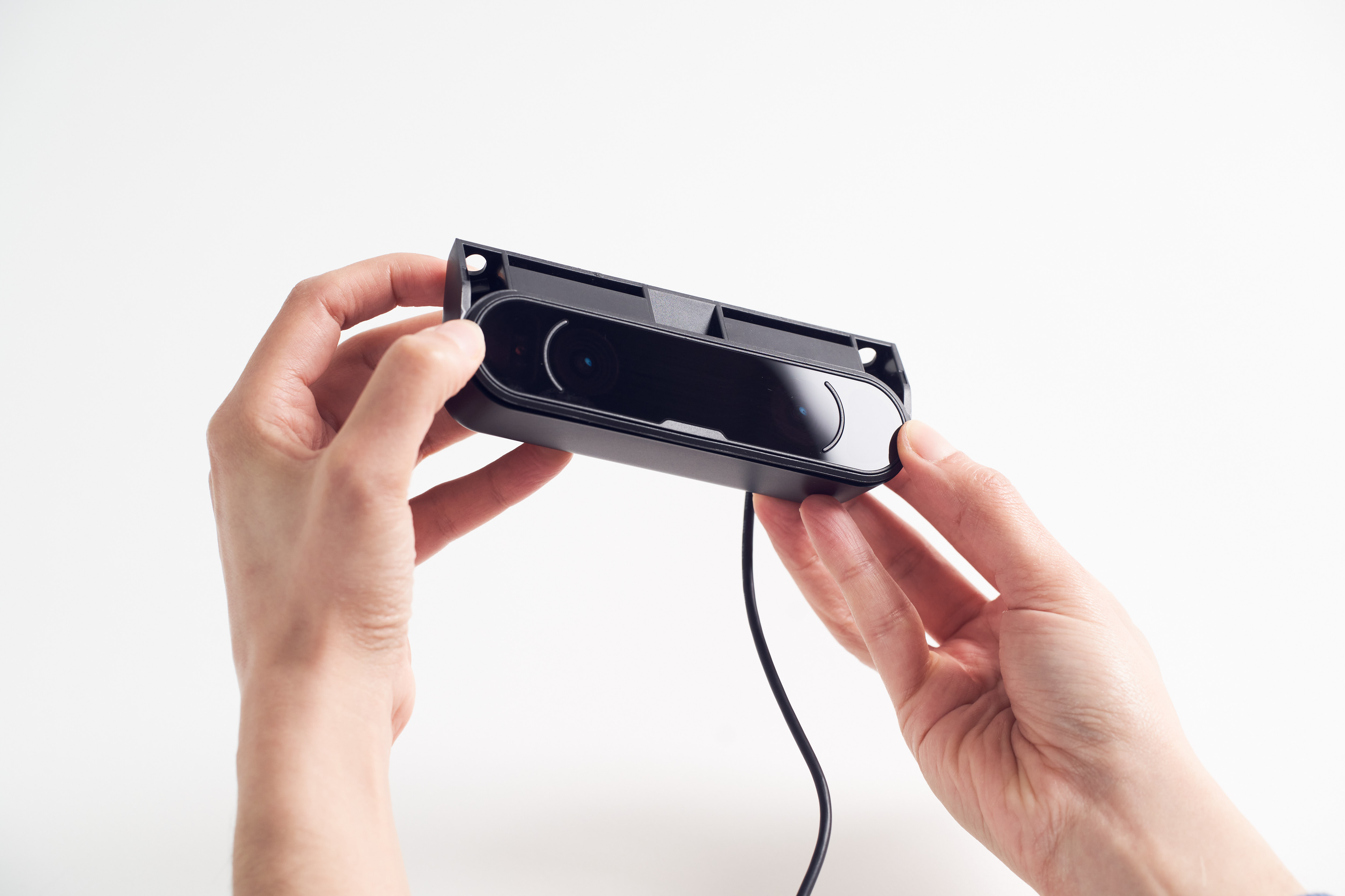
Step 5
The Ultraleap 3Di is now securely attached to the Multi Mount and ready for positioning in desktop mode or fixing to kiosk or screen.
Option 1: Evaluate in desktop mode
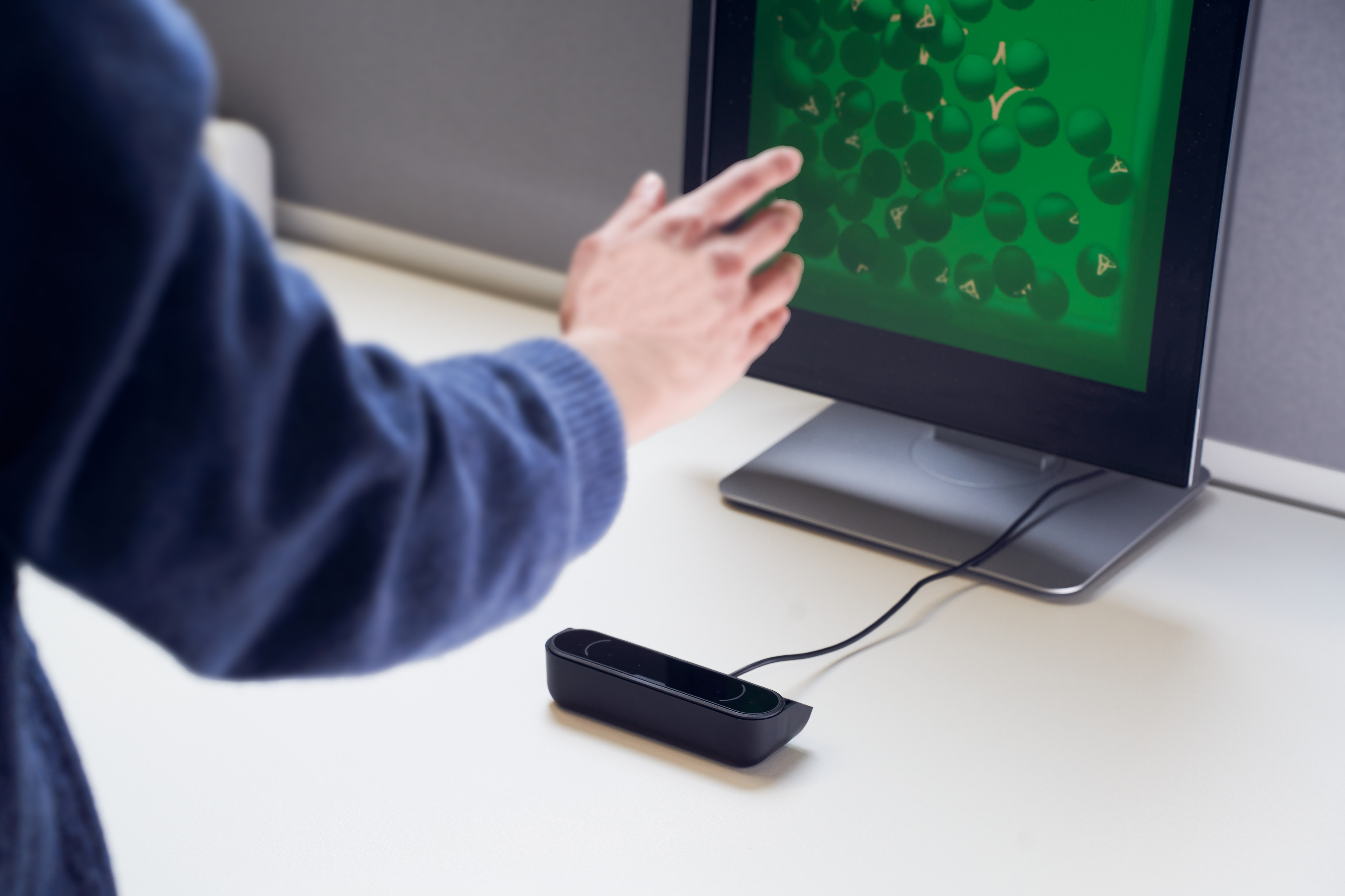
Step 1
Place the Ultraleap 3Di and the Multi Mount on a horizontal surface, in front of a raised display. Position so that the cable exit is pointing towards display.
Option 2: Evaluate on kiosk or screen edge
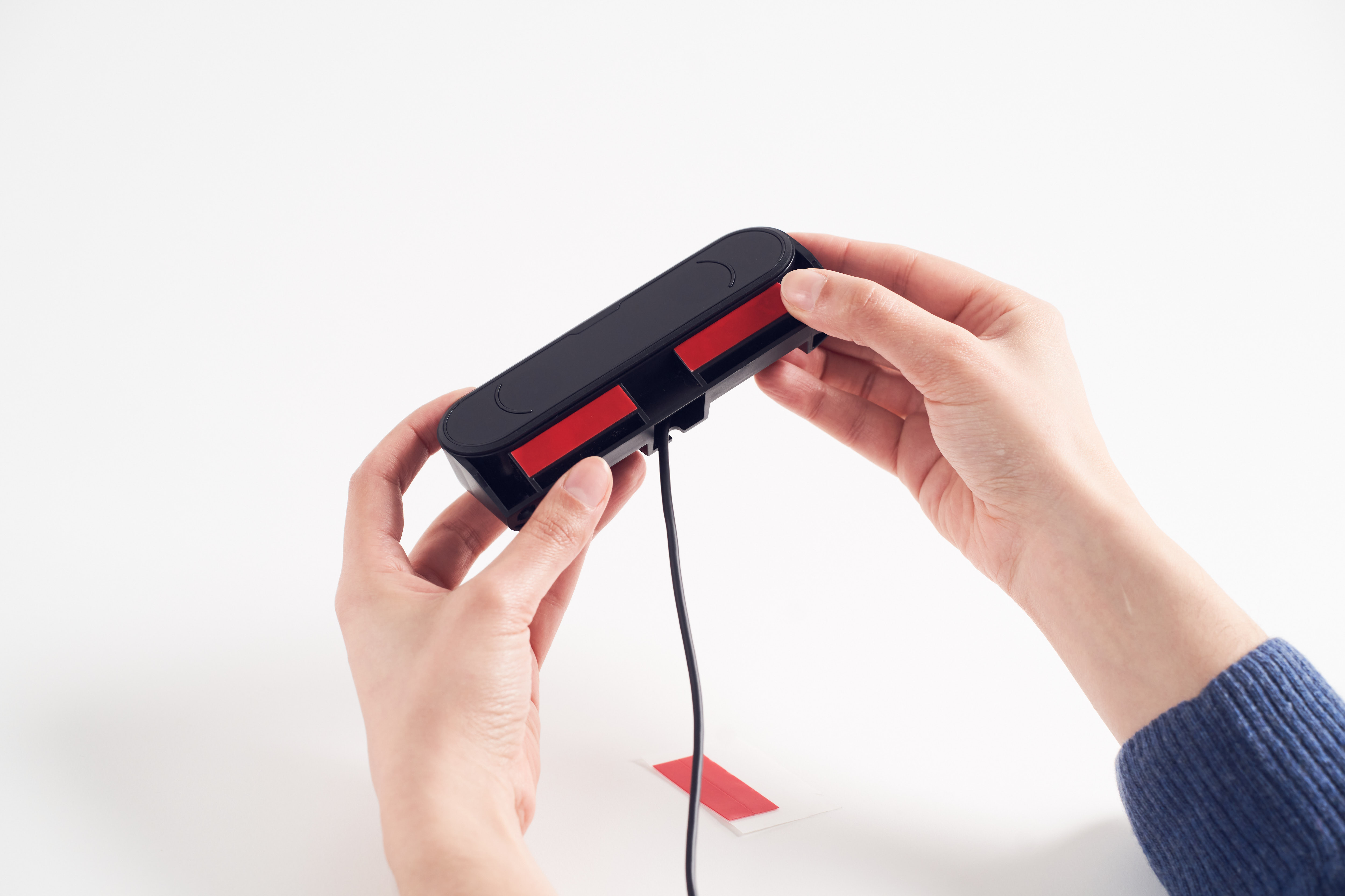
Step 1
Position the adhesive strips on the Multi Mount as shown in image.
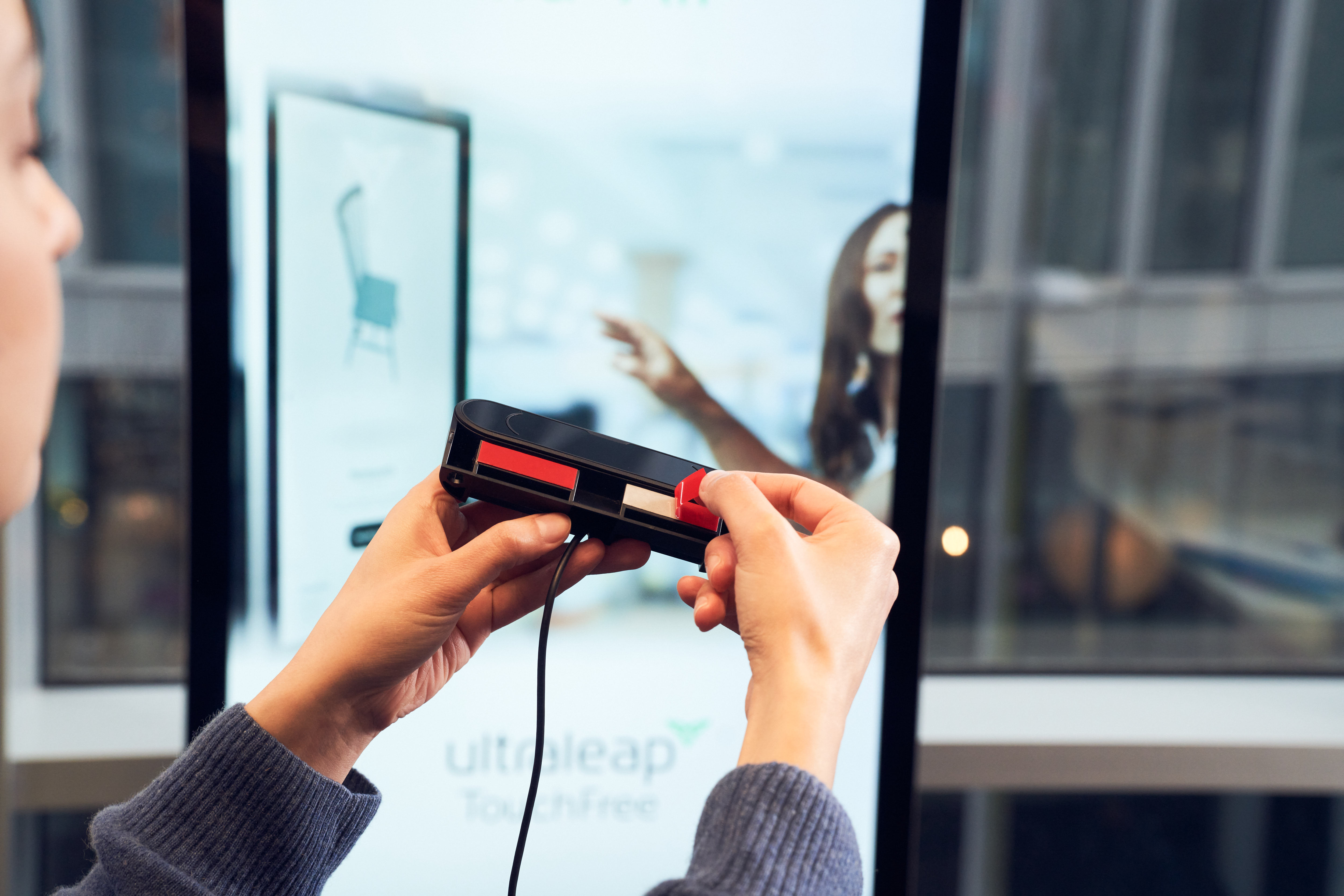
Step 2
Peel off red backing paper on both strips being careful not to touch the sticky underside.
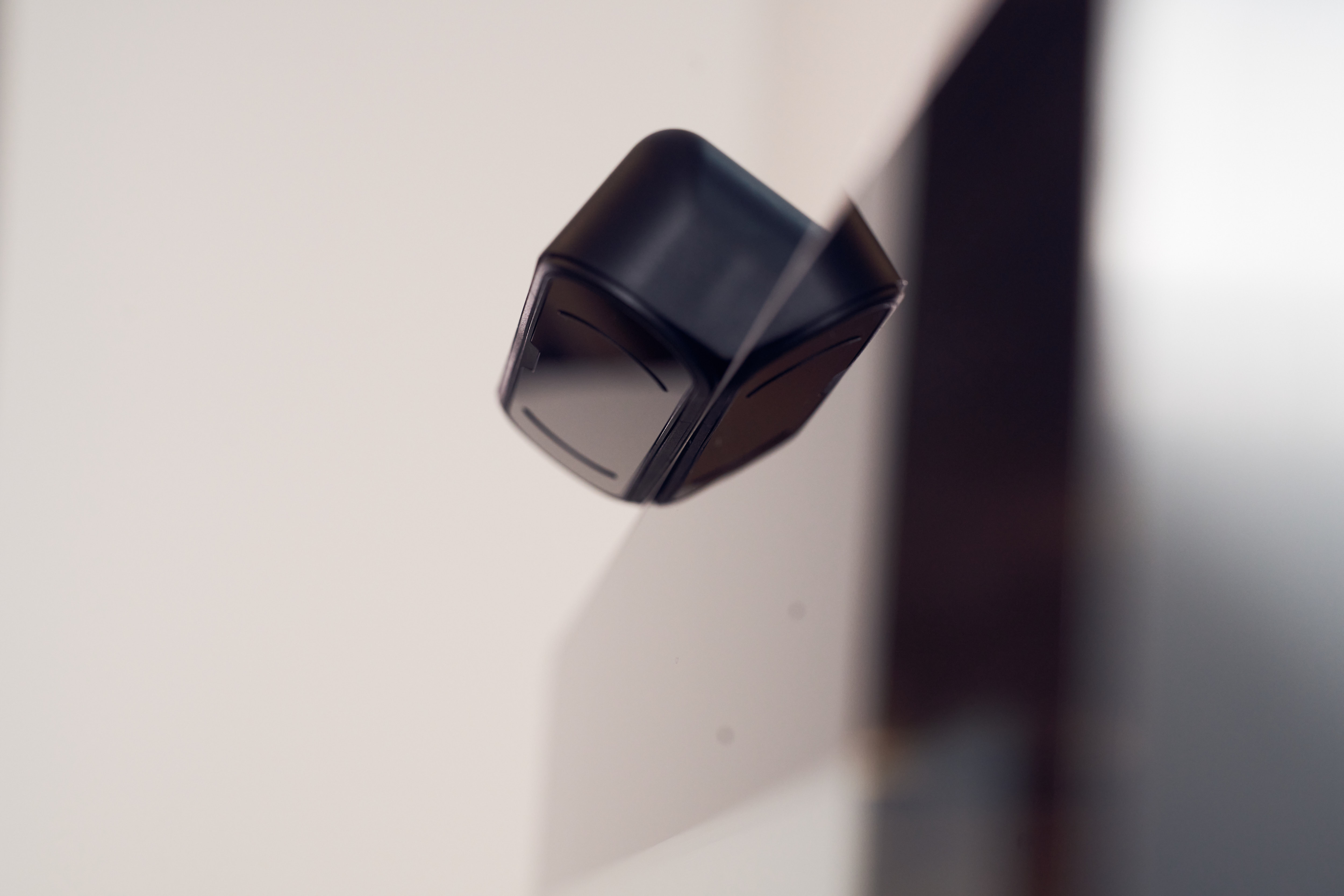
Step 3
Position on chosen kiosk or screen edge so the camera screen is pointing either down if placed at top, or pointing up if placed at bottom.
Option 3: Evaluate directly on kiosk or screen
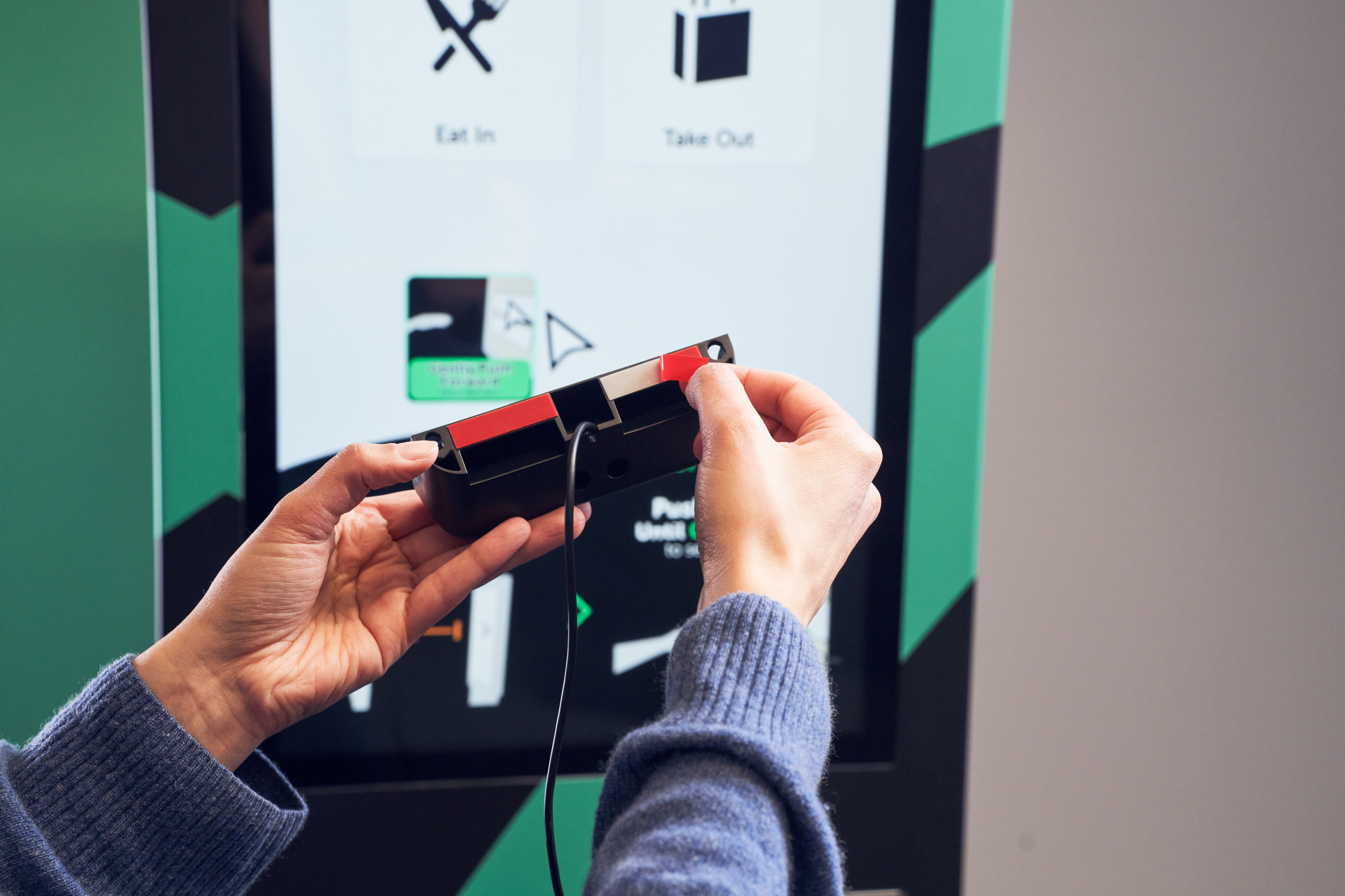
Step 1
Position the adhesive strips on the Multi Mount either side of the cable exit as shown in image.
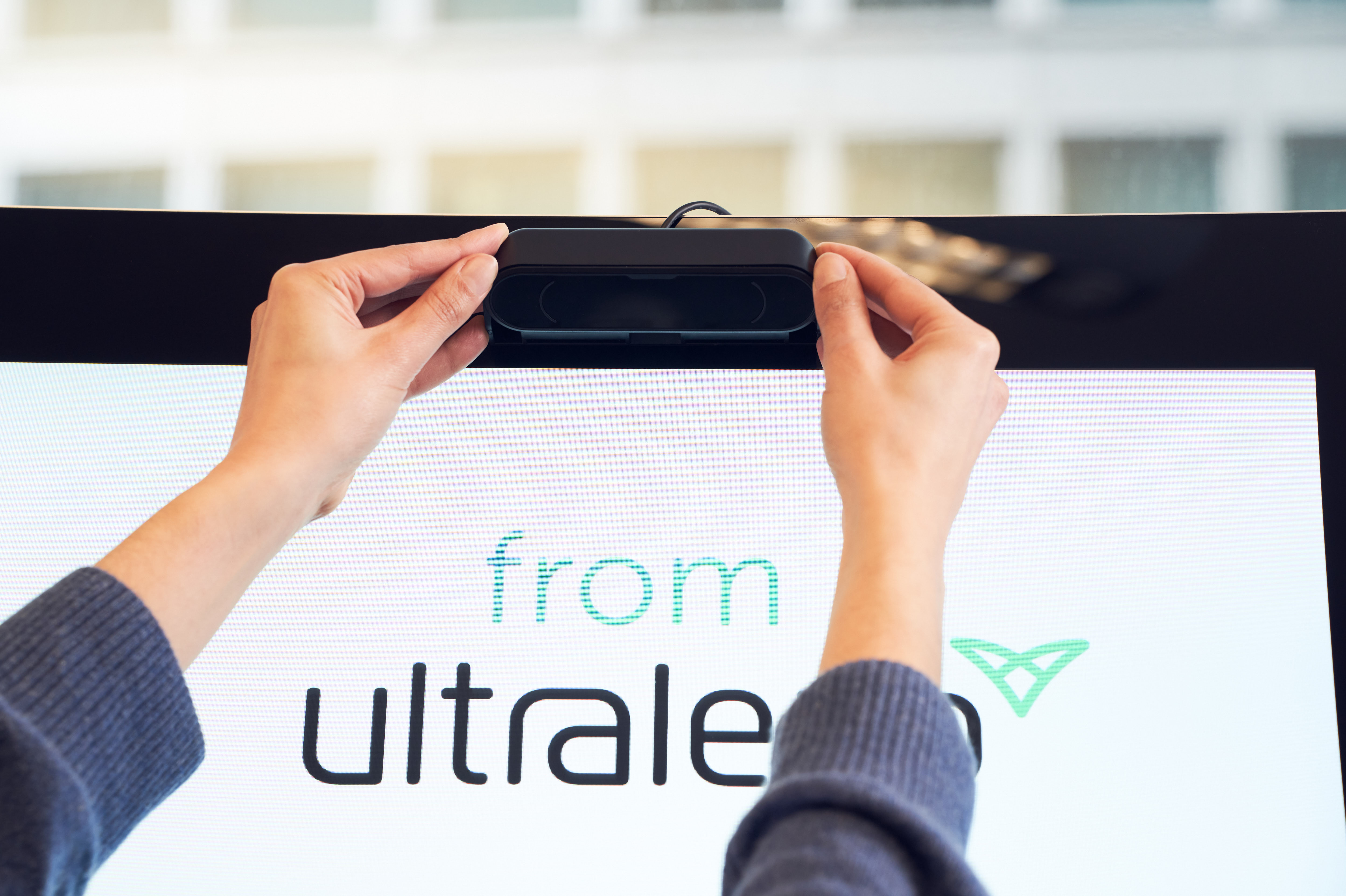
Step 2: Option A
Peel off the red backing paper on both strips being careful not to touch the sticky underside and place directly at the top of the kiosk or screen pointing down.

Step 2: Option B
Peel off the red backing paper on both strips being careful not to touch the sticky underside and place directly at the bottom of the kiosk/screen pointing up.
Panel Mount Kit
The Panel Mount Kit is a permanent mounting solution, protecting the camera, cable, and connection from users and the elements. Use the Panel Mount Kit for flush mounting of the 3Di within display panels (supports panel thicknesses from 2- 8 mm).
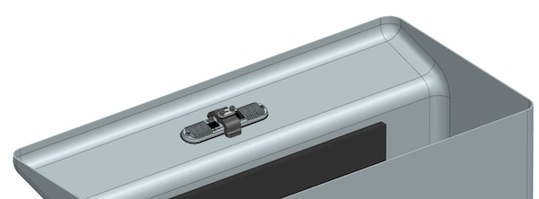
Panel Mount Kit and 3Di viewed from inside kiosk
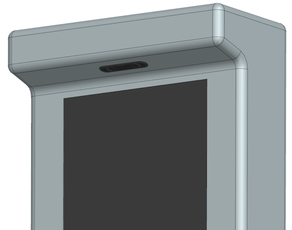
Panel Mount Kit and 3Di viewed from outside kiosk, mounted above screen
To integrate:
Determine shim configuration based on panel thickness from the table below.
Provision for the cutout in the panel.
Configure shims as per the table below. The shims and bracket load from rear of panel, 3Di loads from the front
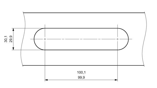
Panel cutout dimensions
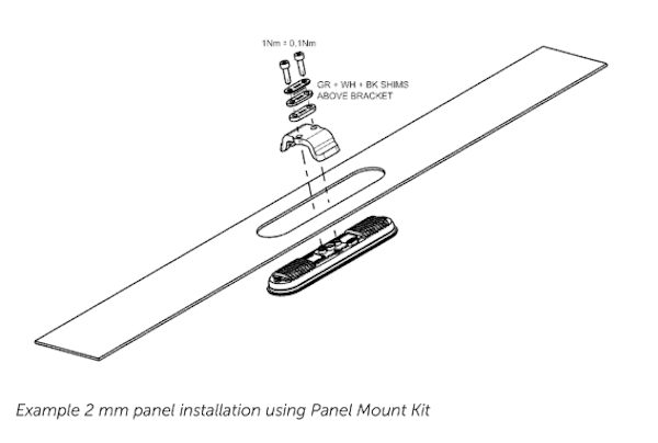
Exploded view of 3Di, panel cutout, and Panel Mount Kit
Panel Thickness |
Shims Above Bracket |
Shims Below Bracket |
|---|---|---|
2 mm |
GR + WH + BK |
– |
3 mm |
WH + BK |
GR |
4 mm |
GR + BK |
WH |
5 mm |
GR + WH |
BK |
6 mm |
WH |
GR + BK |
7 mm |
GR |
WH + BK |
8 mm |
– |
GR + WH + BK |